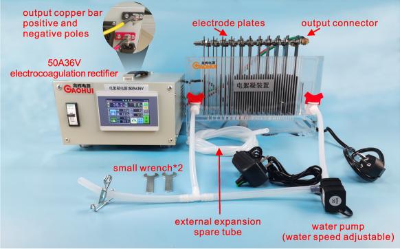
The 50A 36V Electrocoagulation Rectifier is a specialized industrial power supply designed for electrochemical wastewater treatment systems. This high-efficiency DC rectifier provides precise 36-volt, 50-amp output for electrocoagulation (EC) processes, ensuring optimal performance in water purification applications.
| Commonly Used Water Treatment Power Supply Models (Custom models are available if not listed in the table). | |||||||
| Model | Output current A | Output voltage V | Power KW | Input current A | Input voltage V | Weight (KG) | Width W * Length L * Height H |
| GH10024 | 100A | 24V | 2.4 | 12 | 220 | 17 | 380*400*170 |
| GH100100 | 100A | 100V | 10 | 17 | 380 | 40 | 450*500*225 |
| GH120100 | 120A | 100V | 12 | 20 | 380 | 40 | 450*500*225 |
| GH20015 | 200A | 15V | 3 | 15 | 220 | 17 | 380*400*170 |
| GH20024 | 200A | 24V | 4.8 | 8 | 380 | 40 | 450*500*225 |
| GH20036 | 200A | 36V | 7.2 | 12 | 380 | 40 | 450*500*225 |
| GH20048 | 200A | 48V | 9.6 | 16 | 380 | 40 | 450*500*225 |
| GH200100 | 200A | 100V | 20 | 33 | 380 | 130 | 510*580*920 |
| GH30024 | 300A | 24V | 7.2 | 12 | 380 | 40 | 450*500*225 |
| GH30036 | 300A | 36V | 10.8 | 18 | 380 | 40 | 450*500*225 |
| GH30048 | 300A | 48V | 14.4 | 24 | 380 | 95 | 510*580*690 |
| GH300100 | 300A | 100V | 30 | 50 | 380 | 130 | 510*580*920 |
| GH33030 | 330A | 30V | 9.9 | 16.5 | 380 | 40 | 450*500*225 |
| GH40030 | 400A | 30V | 12 | 20 | 380 | 40 | 450*500*225 |
| GH50024 | 500A | 24V | 12 | 20 | 380 | 95 | 510*580*690 |
| GH50036 | 500A | 36V | 18 | 30 | 380 | 95 | 510*580*690 |
| GH50048 | 500A | 48V | 24 | 40 | 380 | 95 | 510*580*690 |
| GH50012 | 500A | 12V | 6 | 10 | 380 | 45 | 380*400*170 |
| GH60048 | 600A | 48V | 28.8 | 48 | 380 | 95 | 510*580*920 |
| GH100024 | 1000A | 24V | 24 | 40 | 380 | 95 | 510*580*690 |
| GH100036 | 1000A | 36V | 36 | 60 | 380 | 130 | 510*580*920 |
| GH100048 | 1000A | 48V | 48 | 80 | 380 | 130 | 510*580*920 |
| GH100012 | 1000A | 12V | 12 | 20 | 380 | 45 | 480*525*310 |
| GH200024 | 2000A | 24V | 48 | 80 | 380 | 130 | 510*580*920 |
| GH300024 | 3000A | 24V | 72 | 120 | 380 | 165 | 530*600*1200 |
| GH4000100 | 4000A | 100V | 400 | 667 | 380 | 195 | 580*650*1400 |
| GH800036 | 8000A | 36V | 288 | 480 | 380 | 235 | 600*680*1600 |
| GH1000036 | 10000A | 36V | 360 | 600 | 380 | 260 | 800*1350*1510 |
Electrochemical methods are used to produce a variety of electrochemical reactions, including electrooxidation, electroreduction, electrocoagulation, electroflotation.

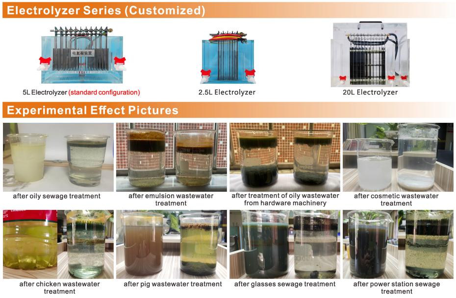
In water treatment, it can remove turbidity, decolorization, algae removal, fluoride removal, ironremoval and other total metal ions, and also it has the function of sterilization and disinfection. It plays a role in flocculation and sedimentation, decolorization, degradation of COD, ammonianitrogen, silicon removal, etc, in drainage treatment. Especially for some high-difficulty wastewater treatment, it has an incomparable effect. currently, it is widely used in the oil field and oil well fracturing flowback fuid reinjection water treatment, anodizing decolorization and phosphorus removal water treatment.
The water treatment power supply primarily consists of a rectifier-filter circuit, a full-bridge converter circuit, a high-frequency transformer, a high-frequency rectifier-filter circuit, an auxiliary power circuit, and a main control unit. The main control unit circuit mainly comprises phase loss protection, temperature protection, overload protection, short-circuit protection, and a PWM circuit with PI regulation.
The three-phase grid voltage is rectified and filtered after passing through the power switch, yielding a smoothed 520VDC supply for the inverter circuit. The inverter circuit primarily employs high-power MOSFET or IGBT modules to form a full-bridge converter. When the PWM output control signal drives the power modules through isolated drivers, two sets of diagonal transistors conduct alternately. This generates a high-frequency pulse voltage in the primary winding of the high-frequency transformer. The secondary voltage is transformed by the high-frequency transformer, rectified, and then supplies energy to the load.
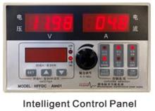
The power supply can operate in either voltage-regulated current-limited mode or current-regulated voltage-limited mode, with seamless switching between the two states.
DC output voltage regulation accuracy ranges from 50% to 100%. When input voltage fluctuates by 10% or load changes occur, the output voltage remains stable with regulation accuracy ≤0.5%.
Incorporates filtering functionality to prevent interference with instruments during power-up, eliminate grid pollution, and mitigate current inrush phenomena.
Automatically locks out when any phase is missing from the three-phase AC input. Resumes operation automatically after fault resolution.
Automatically enters overcurrent shutdown and alarm state when current exceeds rated value.
In case of load short-circuit or internal component short-circuit, the circuit breaker automatically disconnects the power supply.
When abnormal temperatures of semiconductor components (e.g., IGBT, Schottky diodes) reach ≥80°C, the electronic switch on the main control board activates, locking the power supply to effectively protect the unit.
The experimental setup primarily features a 50A 36V electrocoagulation power supply, an electrolysis tank, electrode plates, an adjustable-speed water pump, and associated wiring. The power supply accepts a standard 220V input and delivers a 50A 36V output for wastewater treatment.
The water circulation system simulates real-world water flow, though it also operates independently with dedicated inlet and outlet ports. Users can adjust the electrode spacing, ensuring high experimental flexibility and testing accuracy. This system supports simulations of various wastewater treatment processes, such as electrocoagulation, electro-Fenton oxidation, and electrocatalytic oxidation (please consult customer service for details). After identifying optimal results through testing, operators can record the parameters for future engineering design and cost estimation.